---
title: RS-485 Serial Device Wiring & Connection Guide
description: Avoid bus contention, signal reflections, and communication faults. Learn correct RS-485 daisy-chain wiring, termination placement, and converter setup for Modbus RTU.
---
[Skip to content](https://kb.alleantia.com/rs-485-serial-device-wiring-connection-guide#main-content)
English
Show submenu for translations
![Alleantia\_ATJ\_whitelogocolorbandtrasnpbg\_HR-Oct-21-2021-02-02-26-19-PM.png\]](https://kb.alleantia.com/hs-fs/hubfs/Alleantia_ATJ_whitelogocolorbandtrasnpbg_HR-Oct-21-2021-02-02-26-19-PM.png?height=40&name=Alleantia_ATJ_whitelogocolorbandtrasnpbg_HR-Oct-21-2021-02-02-26-19-PM.png)
Open main navigation
Close main navigation
- English
Show submenu for translations
- [Visit our site](https://www.alleantia.com/)
[Visit our site](https://www.alleantia.com/)
Welcome to Alleantia, Industrial IoT Edge Gateway. How can we help you?
- There are no suggestions because the search field is empty.
1. [Alleantia Knowledge Base](https://kb.alleantia.com/)
2. [Connectivity](https://kb.alleantia.com/connectivity)
# RS-485 Serial Device Wiring & Connection Guide
## This article explains how to correctly wire RS-485 devices onto a single communication line, covering daisy-chain topology, line termination, and the one-converter-per-line rule — for Modbus RTU and similar half-duplex buses to prevent signal reflections, bus contention, and communication faults.
This document describes how to correctly wire RS-485 serial devices onto a single communication line and how to interface that line to an Ethernet network. It defines the required daisy-chain bus topology, the placement of line termination, and the rule that **each RS-485 line must use exactly one RS-485/Ethernet converter.** The guidance applies to common multidrop RS-485 buses such as Modbus RTU and similar half-duplex two-wire systems.
Following these rules prevents signal reflections, bus contention, address conflicts, and the intermittent communication faults that result from incorrect cabling.
2\. RS-485 Fundamentals
RS-485 (TIA/EIA-485) is a balanced, differential signaling standard. Each signal is carried as the voltage difference between two conductors, conventionally named **A (D−)** and **B (D+)**. Because the receiver reads the difference between the two wires, electrical noise that couples equally onto both conductors is largely cancelled, which is what allows RS-485 to run reliably over long distances.
Key electrical characteristics to keep in mind during installation:
- **Half-duplex, two-wire multidrop:** one twisted pair is shared by all nodes; only one device transmits at a time.
- **Up to 32 unit loads** on a standard segment (more with low-load ¼ or ⅛-load transceivers, or with repeaters).
- **Bus length up to ~1200 m** at low data rates; maximum length decreases as baud rate increases.
- **A signal common (GND) reference** should be carried between nodes so the transceivers share a comparable ground potential.
- **Bus contention:** two drivers can enable simultaneously, fighting over the line and corrupting frames.
- **Ambiguous mastering:** two polling masters on the same pair cause overlapping requests and timeouts.
- **Address and response collisions:** device replies collide and cannot be reliably matched to a request.
- **Set one baud rate** for the whole line and configure the converter to match it.
- **Use the same data/parity/stop format** (e.g. 8-N-1) on every node.
- **Group devices by capability:** if speeds cannot be made equal, use additional lines and converters.
- **Shielded twisted-pair (STP)** with characteristic impedance near 120 Ω; one twisted pair for A/B plus a conductor (or second pair) for signal common.
- **Connect the shield to ground at one end only** to avoid ground loops; do not use the shield as the signal return.
- **Maintain the twist** right up to the terminals and keep the A/B pair together for the whole run.
- **One per line:** use a single ATC-1200 as the only converter on the RS-485 bus; place it at one physical end of the daisy-chain.
- **2-wire RS-485 wiring:** connect the bus A (D+) and B (D−) to the corresponding RS-485 terminals on the removable block, plus signal GND, and carry the same pair through to the next device.
- **Matched serial settings:** set the ATC-1200's baud rate, data bits, parity and stop bits to exactly match every device on the line (e.g. 9600, 8-N-1).
- **Termination:** enable the ATC-1200's built-in terminator because it sits at one end of the line; enable termination on the last device too, and disable it everywhere in between.
- **Operating mode:** for a host polling Modbus RTU slaves, configure the unit as a TCP server (or Modbus TCP-to-RTU gateway) so the host reaches every slave by its node address over Ethernet.
- **Network setup:** assign the ATC-1200 a fixed IP appropriate for your LAN and set the listening TCP port used by the host software.
3\. Correct Bus Topology: Daisy-Chain
RS-485 must be wired as a **single linear bus (daisy-chain)**: the cable runs from the converter to the first device, then from that device to the next, and so on, until it reaches the last device. The bus enters and leaves each node on the same terminals, forming one continuous line with two physical ends.
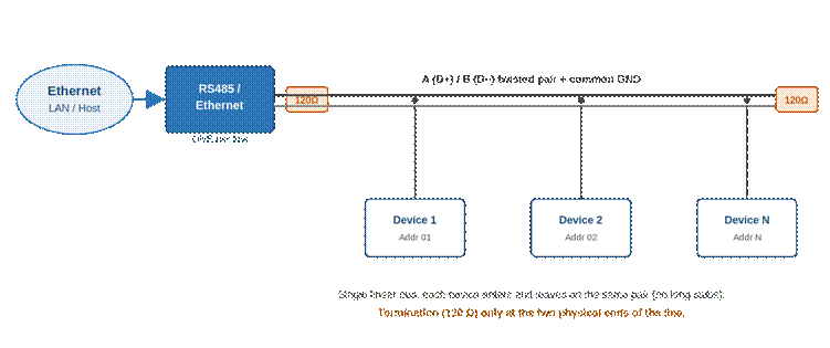
*Figure 1 — Correct RS-485 daisy-chain: one converter at one end, devices chained along a single pair, 120 Ω termination at both ends.*
3.1 Why a linear bus is required
At RS-485 signalling speeds the cable behaves as a transmission line. A single straight run with matched termination at both ends absorbs the signal cleanly. Any branch or “spur” off the main line creates an impedance discontinuity that reflects energy back onto the bus, distorting the waveform and causing bit errors.
3.2 Stubs (drop cables)
If a device cannot sit directly on the trunk, the connecting stub must be kept as short as possible — ideally a few centimetres and never more than a small fraction of the signal rise-time distance. Long stubs effectively turn a clean bus into a star and must be avoided.
4\. Termination and Biasing 4.1 Termination resistors
Place one termination resistor, typically **120 Ω** (matching the cable's characteristic impedance), at **each of the two physical ends** of the bus — and only there. In a typical installation this means one resistor at the converter (one end of the line) and one at the last device in the chain. Devices in the middle must **not** have their termination enabled.
Many converters and field devices include a built-in 120 Ω terminator selectable by a jumper or DIP switch. Enable it only on the two end nodes; leave it disabled everywhere else. Adding extra terminators in the middle overloads the drivers and reduces signal amplitude.
4.2 Fail-safe biasing
When no device is transmitting, the bus is idle (high-impedance) and its state is undefined, which can produce spurious characters. A pair of **bias resistors** (pull-up on A/D+ to Vcc and pull-down on B/D− to ground) holds the idle line in a known state. Apply biasing at **one point only** on the bus — most often inside the converter, where it is frequently built in.
5\. One RS-485/Ethernet Converter per Line
Each RS-485 line must be connected to the Ethernet network through **exactly one RS-485/Ethernet converter (serial device server / gateway).** That single converter is the master/gateway for the line and sits at one physical end of the daisy-chain.
Do not place two or more converters on the same RS-485 line. On a half-duplex two-wire bus only one master may drive the pair at a time. Two converters create the problems shown below:
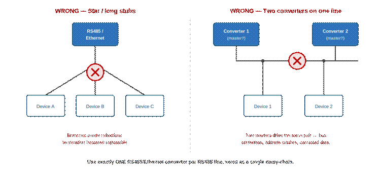
*Figure 2 — Incorrect topologies to avoid: star wiring with long stubs (left) and two converters sharing one RS-485 line (right).*
If you need more devices than one line can carry, or devices that are physically far apart, use **separate RS-485 lines, each with its own single converter**, or insert an RS-485 repeater to extend a single line while preserving the linear topology.
5.1 One protocol per line
All devices sharing a single RS-485 line must speak the **same application protocol** (for example, all Modbus RTU, or all of a single vendor-specific protocol). The bus is a shared medium with no inherent way to separate traffic of different protocols. Mixing, for instance, Modbus RTU devices with devices that use an incompatible framing or command set on the same pair causes each device to misinterpret the other's frames, producing checksum errors, false responses and lost communication.
If you must operate devices that use different protocols, place each protocol on its **own dedicated RS-485 line with its own converter.**
5.2 One serial speed (baud rate) and frame format per line
Every device on the line must also be configured with **identical serial parameters**: the same baud rate (bit/s) and the same frame format — data bits, parity and stop bits. RS-485 has no auto-negotiation; the bit timing is fixed by the configured baud rate.
If two devices use different baud rates, a frame transmitted at one speed is sampled at the wrong bit intervals by a device set to another speed. The result is corrupted bytes, framing/parity errors and devices that never respond. A device that only supports, say, 9600 bps cannot share a line with one fixed at 19200 bps — they must be split onto separate lines (each with its own converter set to the matching speed).
6\. Modbus Addressing
Modbus RTU is the most common application protocol carried over RS-485. It is a strict **master/slave (client/server) protocol**: a single master initiates every exchange and each slave only replies when it is addressed. When the RS-485 line is bridged to Ethernet, the converter (or the host application behind it) acts as the master that polls the slaves.
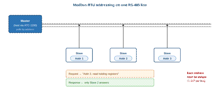
*Figure 4 — Modbus RTU on one RS-485 line: the master polls a device by its node address; only the addressed slave replies. Every node address must be unique.*
6.1 Node (slave) address
Each device on the bus has a **unique node address**, normally set by DIP switches or in the device's configuration. The Modbus standard defines the following ranges for the address byte:
| **Address** | **Meaning** |
| --- | --- |
| 0 | Broadcast — sent to all slaves, no reply expected |
| 1 – 247 | Valid individual slave addresses (assignable) |
| 248 – 255 | Reserved by the standard |
The master places the target address in the first byte of every request. Only the slave with that address processes the request and answers; all other nodes ignore it. **Two devices with the same address on one line will both try to reply, colliding on the bus and corrupting the response** — so every node address on a line must be unique.
6.2 Data model and register addressing
Separate from the node address, Modbus organises a device's data into four tables. Reading or writing a value requires its **register/data address** within the relevant table:
| **Reference (convention)** | **Object type** | **Access** |
| --- | --- | --- |
| 0xxxx | Coils (single bits) | Read / Write |
| 1xxxx | Discrete inputs (single bits) | Read only |
| 3xxxx | Input registers (16-bit) | Read only |
| 4xxxx | Holding registers (16-bit) | Read / Write |
Watch the **off-by-one convention**: documentation often lists a register by a 1-based reference such as 40001, while the address actually transmitted on the wire is 0-based. Holding register “40001” is sent as protocol address 0, “40002” as address 1, and so on. Always confirm whether a device's manual lists 1-based references or 0-based protocol addresses before mapping registers.
In summary, two distinct concepts both use the word “address”: the **node address** identifies the device on the RS-485 line, while the **register address** identifies a data item inside that device.
7\. Terminal-Level Wiring
Connect the bus terminals consistently from node to node: **A→A, B→B, and GND→GND**. Keeping polarity identical along the whole line is essential; a single swapped A/B pair will break communication for every node beyond it.
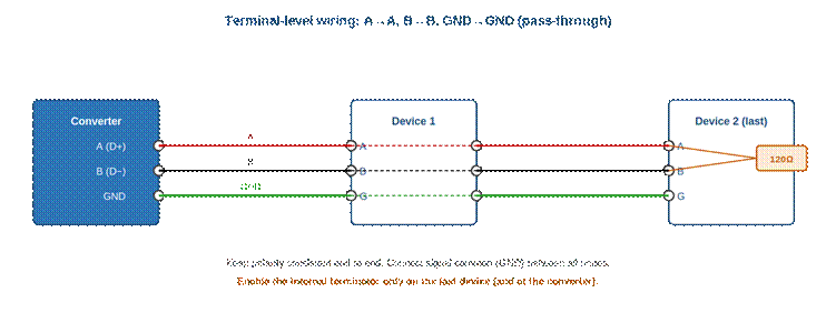
*Figure 3 — Pass-through wiring at the terminal block: A, B and common ground are carried through every node; termination is enabled only at the last device.*
7.1 Recommended cable 8. Example Converter: ATC-1200
The ATC-1200 is a representative low-cost industrial serial device server that illustrates how a single converter terminates one RS-485 line and bridges it to Ethernet. It is a 3-in-1 unit offering RS-232, RS-422 and RS-485 on the same device, selectable by configuration; for an RS-485 multidrop bus you use its RS-485 mode and removable screw terminals.
8.1 Key specifications
| **Parameter** | **ATC-1200** |
| --- | --- |
| Serial interfaces | RS-232 / RS-422 / RS-485 (3-in-1, selectable) |
| RS-485 / RS-422 baud rate | 1200 bps up to 921600 bps |
| RS-232 baud rate | 1200 bps up to 115200 bps |
| Data bits / parity / stop | 5/6/7/8 • none, odd, even • 1, 1.5, 2 |
| RS-485 devices per line | Up to 32 nodes |
| Network | 10/100 Mbps Ethernet, RJ45 |
| Operating modes | Virtual COM (driver), TCP server/client, UDP, pair connection |
| Protocol support | TCP/IP, UDP, DHCP and Modbus TCP gateway |
| RS-485 connection | Removable screw terminals, with surge protection |
| Termination | Built-in selectable terminator |
| Power | 9–24 VDC (9 V adapter included) |
| Mounting / environment | DIN-rail or panel; industrial temperature range |
*Specifications are summarised from the manufacturer/distributor datasheets and may vary by hardware revision; always confirm against the datasheet for your unit.*
8.2 Applying the rules to the ATC-1200 9. Step-by-Step Installation Procedure
1. **Plan the route** so the cable passes each device in sequence, forming one continuous linear path with two clear ends.
2. **Place the converter** at one physical end of the line and connect its A/B/GND terminals to the cable.
3. **Daisy-chain each device** by landing the incoming pair and the outgoing pair on the same A/B/GND terminals, keeping polarity consistent.
4. **Assign a unique address** to every device on the line, and make sure all nodes share the same protocol, baud rate, parity and stop-bit configuration.
5. **Enable termination** (120 Ω) only at the two ends: the converter and the last device. Disable it on all middle devices.
6. **Enable biasing** at a single point, normally the converter.
7. **Verify** continuity and polarity, then configure the converter's IP settings and serial parameters and confirm communication with each device in turn.
10\. Commissioning Checklist
| **Check** | **Requirement** |
| --- | --- |
| Topology | Single linear daisy-chain; no star or branched wiring |
| Converters per line | Exactly one RS-485/Ethernet converter |
| Protocol | Same application protocol on all nodes (e.g. all Modbus RTU) |
| Serial speed / format | Identical baud rate and frame format (e.g. 9600 8-N-1) |
| Node addresses | Unique per device (Modbus 1–247); no duplicates |
| Termination | 120 Ω at both physical ends only |
| Middle devices | Termination disabled |
| Biasing | Enabled at one point (typically the converter) |
| Polarity | A→A and B→B consistent end to end |
| Signal ground | Common GND carried between all nodes |
| Stubs | Kept as short as possible (avoid long drops) |
| Cable | 120 Ω shielded twisted pair, shield grounded one end |
11\. Common Faults and Causes
| **Symptom** | **Likely cause** |
| --- | --- |
| No communication at all | Swapped A/B polarity, or no converter / wrong IP-serial settings |
| Intermittent or random errors | Missing or excess termination; long stubs; star wiring |
| Only the first devices respond | Polarity swapped or break in the chain further along the bus |
| Garbage when idle | No fail-safe biasing on the bus |
| Frequent timeouts / collisions | More than one converter/master, or duplicate node addresses |
| Some devices never reply | Baud rate or frame format mismatch on those nodes |
| Random corruption across the bus | Mixed protocols or mixed baud rates on the same line |
| Errors only at high baud rate | Excessive bus length or poor termination for that rate |
***Golden rules: one linear daisy-chain; one converter per line; one protocol and one baud rate for all nodes; unique addresses; termination at both ends only.***
- [Industrial IoT Connectivity in 4 steps](https://kb.alleantia.com/industrial-iot-connectivity-in-4-steps#main-content)
- [Industrial Connectivity in 5 minutes - Configuration Steps](https://kb.alleantia.com/industrial-iot-connectivity-in-4-steps#industrial-connectivity-in-5-minutes-configuration-steps)
- [Alleantia Platform Overview](https://kb.alleantia.com/alleantia-platform-overview#main-content)
- [Alleantia Core](https://kb.alleantia.com/alleantia-platform-overview#alleantia-core)
- [Cloud Portal](https://kb.alleantia.com/alleantia-platform-overview#cloud-portal)
- [Machine Drivers](https://kb.alleantia.com/alleantia-platform-overview#machine-drivers)
- [IIoT Apps - Connect Business Apps](https://kb.alleantia.com/alleantia-platform-overview#iiot-apps-connect-business-apps)
- [Site Manager](https://kb.alleantia.com/alleantia-platform-overview#site-manager)
- [Alleantia Core](https://kb.alleantia.com/alleantia-core#main-content)
- [Alleantia Core - Download and Configurations](https://kb.alleantia.com/alleantia-core#alleantia-core-download-and-configurations)
- [Licenses and Free Version](https://kb.alleantia.com/licenses-and-free-version#main-content)
- [License Management](https://kb.alleantia.com/licenses-and-free-version#license-management)
- [Alleantia Core - Free Version](https://kb.alleantia.com/licenses-and-free-version#alleantia-core-free-version)
- [Machine Drivers](https://kb.alleantia.com/machine-drivers#main-content)
- [How can I create a driver with spreadsheet template??](https://kb.alleantia.com/machine-drivers#how-can-i-create-a-driver-with-spreadsheet-template)
- [How can I create a driver with Driver Editor?](https://kb.alleantia.com/machine-drivers#how-can-i-create-a-driver-with-driver-editor)
- [Private Library](https://kb.alleantia.com/machine-drivers#private-library)
- [Machines connection configurations](https://kb.alleantia.com/machine-drivers#machines-connection-configurations)
- [Stream Data - IIoT Apps](https://kb.alleantia.com/stream-data-iiot-apps#main-content)
- [API REST](https://kb.alleantia.com/stream-data-iiot-apps#api-rest)
- [Modbus](https://kb.alleantia.com/stream-data-iiot-apps#modbus)
- [OPC UA](https://kb.alleantia.com/stream-data-iiot-apps#opc-ua)
- [AWS](https://kb.alleantia.com/stream-data-iiot-apps#aws)
- [Boomi](https://kb.alleantia.com/stream-data-iiot-apps#boomi)
- [Microsoft Azure](https://kb.alleantia.com/stream-data-iiot-apps#microsoft-azure)
- [Dropbox](https://kb.alleantia.com/stream-data-iiot-apps#dropbox)
- [MQTT](https://kb.alleantia.com/stream-data-iiot-apps#mqtt)
- [SQL](https://kb.alleantia.com/stream-data-iiot-apps#sql)
- [OneDrive for Business](https://kb.alleantia.com/stream-data-iiot-apps#onedrive-for-business)
- [TeamViewer](https://kb.alleantia.com/stream-data-iiot-apps#teamviewer)
- [Alleantia Certified Hardware](https://kb.alleantia.com/alleantia-certified-hardware#main-content)
- [Advantech](https://kb.alleantia.com/alleantia-certified-hardware#advantech)
- [Cisco](https://kb.alleantia.com/alleantia-certified-hardware#cisco)
- [Dell](https://kb.alleantia.com/alleantia-certified-hardware#dell)
- [Eurotech](https://kb.alleantia.com/alleantia-certified-hardware#eurotech)
- [Lenovo](https://kb.alleantia.com/alleantia-certified-hardware#lenovo)
- [Portwell](https://kb.alleantia.com/alleantia-certified-hardware#portwell)
- [Stratus](https://kb.alleantia.com/alleantia-certified-hardware#stratus)
- [Simulators and Starter Kit Industria 4.0](https://kb.alleantia.com/simulators-and-starter-kit-industria-4-0#main-content)
- [Simulators - PLCs, CNC, Energy meters](https://kb.alleantia.com/simulators-and-starter-kit-industria-4-0#simulators-plcs-cnc-energy-meters)
- [Starter Kit Industria 4.0](https://kb.alleantia.com/simulators-and-starter-kit-industria-4-0#starter-kit-industria-4-0)
- [Edge Operational Applications](https://kb.alleantia.com/edge-operational-applications#main-content)
- [Cobot Smart Service](https://kb.alleantia.com/edge-operational-applications#cobot-smart-service)
- [FAQs - Trouble Shooting](https://kb.alleantia.com/faqs-trouble-shooting#main-content)
- [Configurations](https://kb.alleantia.com/faqs-trouble-shooting#configurations)
- [System Setup](https://kb.alleantia.com/faqs-trouble-shooting#system-setup)
- [Interfaces to IIoT Apps](https://kb.alleantia.com/faqs-trouble-shooting#interfaces-to-iiot-apps)
- [Interfaces to Industrial Devices](https://kb.alleantia.com/faqs-trouble-shooting#interfaces-to-industrial-devices)
- [Connectivity](https://kb.alleantia.com/connectivity)
[](http://www.alleantia.com)
© 2024 Alleantia s.r.l
Copyright © 2026, ALLEANTIA SRL